This is the second part of my shadow mapping tutorial (find part 1 here). I am going to discuss some of the issues of the shadow mapping technique as well as some basic solutions to the problem. I’m also going to attach a demo application, in which you can play around with some of the shadow mapping variables and techniques. I do have to mention that the demo was a very quickly programmed prototype. It serves its purpose as a demo application but I dont advise cutting and pasting the code into your own projects as a lot of the techniques used arent exactly optimal. Not to mention that I did take a few shortcuts here and there.
Anyways back to shadow mapping, the reason for this tutorial is that there are two main issues with the shadow mapping technique discussed in the first part of the tutorial, namely:
- Self-shadowing (surface acne)
- Shadow Quality
NOTE: a fragment is the data structure that enters the pixel shader (has a clip space position, and a clip space depth). Each fragment corresponds to a single pixel in the render target.
Self-Shadowing
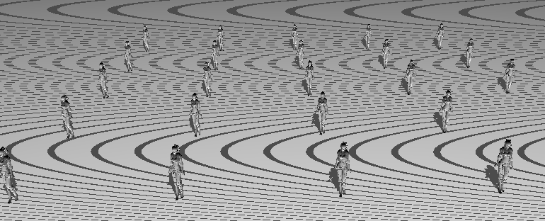
The first major problem is that objects in our scene tend to self shadow themselves and in doing so cause pretty severe graphical anomalies. The screenshot below is the result of the shadow mapping technique discussed in part one. The screenshots in part one already have the fix applied.
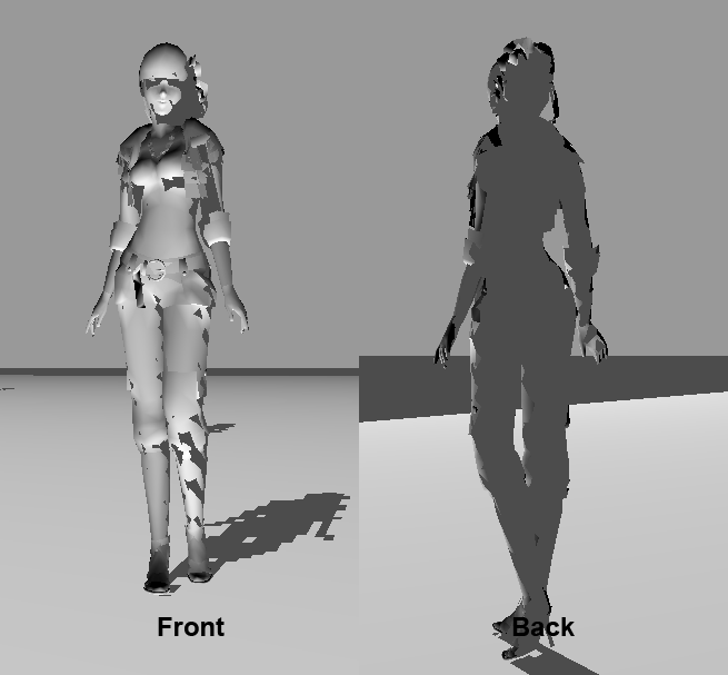
As you can see, the floor in the screenshot exhibits a pretty bad moire pattern due to the shadow mapping technique used. This is not the only problem, if we zoom in on the models in the scene, we see some really bad surface acne or self shadowing. The screenshot below shows the graphic anomalies resulting from the self shadowing on a static mesh, The front of the model exhibits shadowing even though it is directly illuminated by the light source.
PLEASE NOTE: the “girl” model used in the demo application is of pretty bad quality and I suspect a few of the normals are a little screwed up. That model was the best model I could find within the time frame that I had.
So what causes this self-shadowing (often referred to as surface acne) problem?, simply put its an error resulting from the limited precision of the shadow map. If you recall, a depth buffer has limited precision (often 24 or 32bits) with which it needs to represent the entire z range (0-1) of the canonical view volume (for more info refer to my computer graphics course slides – the rasterizer stage). Also important to note is that when using a perspective projection, the depth values do not vary linearly across the furstum. Most of the precision is found close to the near plane making the depth buffer less accurate the closer to the far plane a point is.
The shadow map’s lack-of-precision (and resulting self shadowing issues) is one of the biggest problems of the shadow mapping technique. To ameliorate this it’s usually a good idea to try and keep the precision in the shadow map as high as possible. This can be done by setting the near and far planes of the light volume as close to the scene objects as possible while keeping the entire illuminated area in view. So dont set the near plane to 0.1 units if the first object to be illuminated will never be closer that 10 units from the light.
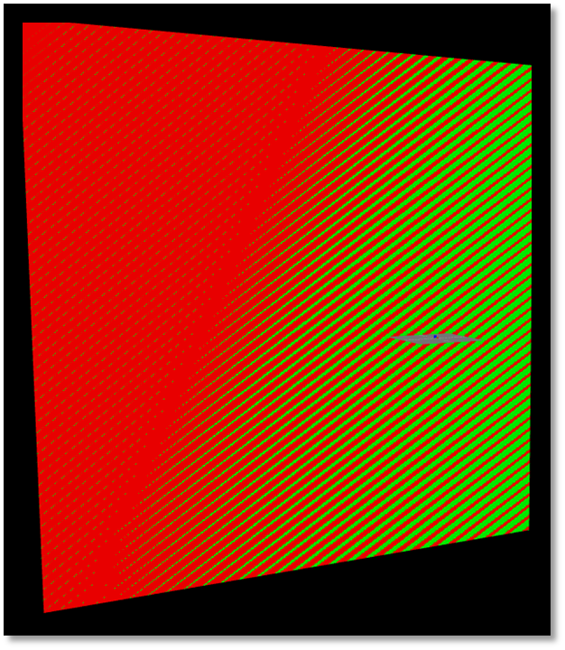
The precision problem of the depth buffer is called z-fighting. Z-fighting occurs when two primitives are so close together that due to the limited precision of the depth buffer, their resulting (post-projection) depth value are equal. This precision error means that the primitive from which the final pixel color is picked from, is determined by the view. As the view changes, the choice of primitive often changes and it seems as if the two primitives are flickering in and out of each other (see the below screenshot).
Now the reason I bring up z-fighting is becuase self-shadowing is caused by the same precision problem. The shadow map stores the depth location of the front faces (from the viewpoint of the light) of the occluders. This means that lit/shadowed boundary (shadow boundary) is placed on the those faces of the objects. So once the scene is rendered from the viewpoint of the camera, the depth values for any faces visible to the camera that are also visible to the light once converted back into light space may, due to the limited precision of the depth buffer, differ to those already stored within the shadow map. If this difference results in the fragments of those occluding faces having a light space depth value greater than the stored depth value in the shadow map, then that fragment is defined as being in shadow even though that fragment is directly visible to the light. This results in fragments on occluding faces self-shadowing themselves erroneously. Self-shadowing only occurs on the faces of the occluders which are stored in the shadow map.
This is the exact reason why the floor in the first screenshot exhibits the moire shadowing pattern. Since the floor’s depth values are stored within the shadow map once each fragment generated from the floor primitive is projected back into light space, the limited precision might push it behind the stored depth value for the front face of the floor, resulting in those fragments self-shadowing themselves.
There are two solutions to this problem: the first is simply to add a fixed shadow map bias to each fragment’s light space depth before comparing it to the shadow map value. What this does is artificially move the shadow boundary towards the far plane of the light’s view volume. Any projected fragments whose depth values were close to the boundary are now moved in front of the boundary and so will be lit. This basically artifically moves every fragment closer to the light before comparing the depth values. Now the amount of bias necessary to remove self shadowing varies greatly between scenes due to the various light positions, projections, etc, and therefore the bias value often needs to hand tweaked for a scene.
The HLSL code for applying a shadow map bias is shown below:
float4 PS_STANDARD( PS_INPUT input ) : SV_Target
{
	//re-homogenize position after interpolation
	input.lpos.xyz /= input.lpos.w;

	//if position is not visible to the light - dont illuminate it
	//results in hard light frustum
	if( input.lpos.x < -1.0f || input.lpos.x > 1.0f ||
	    input.lpos.y < -1.0f || input.lpos.y > 1.0f ||
	    input.lpos.z < 0.0f  || input.lpos.z > 1.0f ) return ambient;

	//transform clip space coords to texture space coords (-1:1 to 0:1)
	input.lpos.x = input.lpos.x/2 + 0.5;
	input.lpos.y = input.lpos.y/-2 + 0.5;

	//apply shadow map bias
	input.lpos.z -= shadowMapBias;

	//sample shadow map - point sampler
	float shadowMapDepth = shadowMap.Sample(pointSampler, input.lpos.xy).r;

	//if clip space z value greater than shadow map value then pixel is in shadow
	float shadowFactor = input.lpos.z <= shadowMapDepth;

	//calculate ilumination at fragment
	float3 L = normalize(lightPos - input.wpos.xyz);
	float ndotl = dot( normalize(input.normal), L);
	return ambient + shadowFactor*diffuse*ndotl;
}
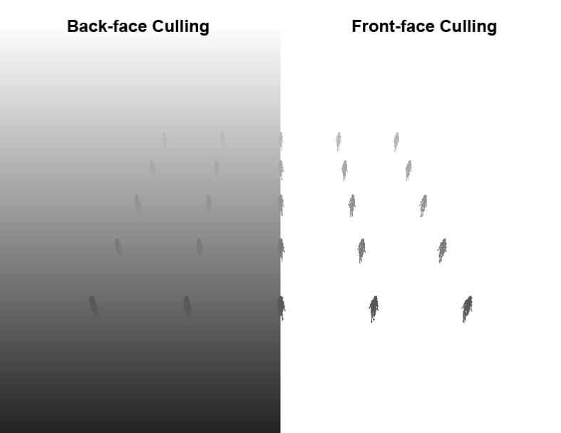
The second solution to the self shadowing problem is to not store the depth values of the front faces of the occluding objects in the shadow map, but rather the depth values of the back faces. Doing so will push the shadow boundary from the front faces to the backfaces of the objects and so remove the problem of front faces being too close to the shadow boundary. The screen shot below shows the shadow map for the same scene just rendered with different culling options enabled.
Unfortunately this technique has two downsides. Firstly it doesnt remove the self shadowing problem it simply moves it to the back faces. This means that now we have back faces that end up being lit when they should be shadowed and a bias term is needed once more. Now this is less of a problem simply due to the fact that the backfaces will often have a zero diffuse and specular light contribution (due to the normals facing away from the light) and so the self-shadowing effect is usually hidden. Another problem which is visible in the above screenshot is that objects which do not have back faces, such as the floor in the above example do not act as occluders. So given a situation where you have renderer a simple quad to represent a wire mesh or chain link fence, that fence will not generate any shadows as there is no back face and so there will be no contribution to the shadow map.
I’ve made a brief video showing the effect of the shadow map bias term as well as the effect of using the back faces for the shadow map generation. As I mentioned the normals on the test model I have are slightly messed up and so the self-shadowing on the backfaces is actually visible. ( I guess the screwed up normals actually came in useful 🙂 )
Shadow Quality
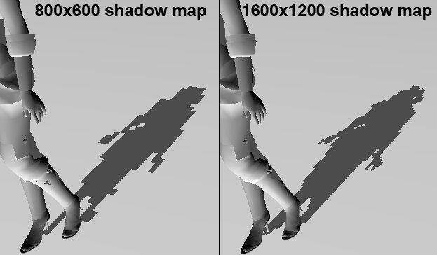
The second major problem with the basic shadow mapping technique is the shadow map quality. The shadow generated through the point sampling shadow map technique discussed is extremely pixelated. The below screenshot shows the extremely pixelated shadows resulting for the point sampling technique. The left hand shadow was generated using a shadow map which was the same size as the render target (800×600) whereas the right hand side was generated using a shadow map 4 times the size of the render target (1600×1200).
The larger shadow map has had a signficant effect of the overall shadow quality but it is often infeasible to use such massive shadow maps, since at standard HD gaming resolutions such as 1920×1080 or 1280×720, you’re looking at around 8MB and 3.5MB just to store the shadow map never mind the increased cost of rendering the scene at such a huge resolution. I’m not going to go into detail regarding alternatives to increasing shadow map size but I’m rather going discuss why increasing the shadow map size improves the quality of the rendered shadows.
Lets consider the contents of the shadow map not as discrete depth values but rather as shadow volumes. Each texel in the shadow map represents a shadow volume from the stored depth to 1. The shape of the shadow volume is derived from the projection used. Now consider the light volume visible in the sample scene. Each texel in the shadow map corresponds to shadow volume that takes up a portion of that light volume. The lower the number of texels in the shadow map, the the larger space each resulting shadow volume takes up of the light volume. This means that all fragments within that region of the light volume will all reference a single texel resulting in the blockiness/pixelation seen. Increasing the number of texels in the shadow map reduces the volume of the resulting shadow volume of each one thereby reducing the overall pixelation. In the screen shot above the size of shadow volumes resulting from each texel are clearly visible.
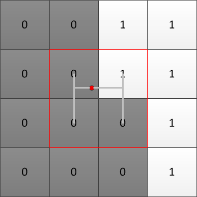
This exact same phenomenon occurs when texture magnification, i.e. when the texel to pixel density is lower than 1, multiple pixel reference the same texel and the result is magnification. When applying texturing, we can improved the quality of magnified texture by simply using a bilinear filter when retrieving texel values. The bilinear filtering returns an interpolated value between the current texel and the 3 nearest texels, resulting in smooth transitions between texel values rather than discrete color changes as pixels cross texel borders. The same approach is used for retrieving shadow map values with one difference: we dont interpolate between the depth values but rather on the shadow factor (0 if in shadow and 1 if lit). So whereas bilinear filtering on a texture would retrieve the 4 texel colors and then interpolated between them to return the final color, we need to retrieve the 4 texel depth values, calculate whether those depth values will result in the current fragment being lit and then interpolate between the shadow factors to return the final shadow factor. This shadow factor interpolation is shown in the below figure.
The reason we dont simply interpolate the depths in the shadow map is due to the fact that after the interpolation we have a depth value which once compared to the projected fragment’s depth value will return either a 1 or a 0 (i.e. shadowed or lit). The end result being that now we’ve simply enlarged the shadow volumes of each texel. This will result in a slightly better shadow due to the enlargement of the shadow volumes but still has a large degree of blockiness. The blockiness is problematic around the edges of the shadow, so what we’d like to do is simply calculate how much in-shadow that pixel is. If a fragment’s shadow map texel is surrounded on all sides by shadowed texels (texels resulting in a 0 value after comparison to the fragment depth) then that fragment is clearly in shadow, but if a fragment’s shadow map texel has a combination of lit texels and shadowed texels then its natural to asusme that texel is on the shadow edge and we calculate how how close to lit that texel is. The end result is shadows with soft (blurred) edges. This shadow map filtering technique is called percentage closer filtering or PCF. Mainly since it returns the shadow percentage of a fragment, i.e. how close to lit that fragment is.
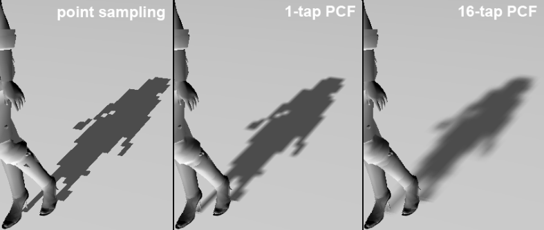
The effects of PCF on the shadow quality are shown below:
As you can see there is marked difference on the edges between the standard point sampling and the 1-tap PCF. The 1-tap refers to how many post-filtering sampling operations we perform. For example, a single sample operation on a texture is a single “tap” irrespective of whether we are using point, bilinear or anisotropic sampling. PCF can be implemented manually by calculating the texel offsets of the nearest 3 texels, then getting the shadow map depth values, performing the comparisons, then manually linearly interpolating between the values or we can simply make use of the API comparison sampler filter. The DX10 and DX11 APIs include comparison sampler options. These samplers do exactly what was described above, read the value from the texture at the 4 texel locations, perform the comparisons at each texel value and return the linear interpolation between the texel comparison results. Creating a comparison sampler is simple enough and requires only that the filter type be changed to one of the comparison ones and that a comparison function be defined. The comparison function defines what type of comparison to perform on the texel values (less than, greater than, less than equals, etc). The HLSL code for the comparison sampler state is shown below:
SamplerComparisonState cmpSampler
{
   // sampler state
   Filter = COMPARISON_MIN_MAG_MIP_LINEAR;
   AddressU = MIRROR;
   AddressV = MIRROR;

   // sampler comparison state
   ComparisonFunc = LESS_EQUAL;
};
There is also a change to how we sample the texture, instead of using the Sample function, we make use of the SampleCmp & SampleCmpLevelZero functions. These two functions are identical the only difference being that SampleCmpLevelZero can only sample the lowest level in a mipmap chain. The DX SDK docs state that the return value of these two function can only be 0 or 1. This is incorrect, and the function return a float value between 0 and 1. When using the SampleCmp function to sample a texture, you will also need to provide a comparison value with which to compare the texel values.
In our case, we simply apply the shadow map bias to the fragment’s light space projected depth, then plug in that value into the SampleCmp function. The HLSL code for 1-Tap PCF is shown below:
float4 PS_PCF( PS_INPUT input ) : SV_Target
{
	//re-homogenize position after interpolation
	input.lpos.xyz /= input.lpos.w;

	//if position is not visible to the light - dont illuminate it
	//results in hard light frustum
	if( input.lpos.x < -1.0f || input.lpos.x > 1.0f ||
	    input.lpos.y < -1.0f || input.lpos.y > 1.0f ||
	    input.lpos.z < 0.0f  || input.lpos.z > 1.0f ) return ambient;

	//transform clip space coords to texture space coords (-1:1 to 0:1)
	input.lpos.x = input.lpos.x/2 + 0.5;
	input.lpos.y = input.lpos.y/-2 + 0.5;

	//apply shadow map bias
	input.lpos.z -= shadowMapBias;

	//basic hardware PCF - single texel
	float shadowFactor = shadowMap.SampleCmpLevelZero( cmpSampler, input.lpos.xy, input.lpos.z );

	//calculate ilumination at fragment
	float3 L = normalize(lightPos - input.wpos.xyz);
	float ndotl = dot( normalize(input.normal), L);
	return ambient + shadowFactor*diffuse*ndotl;
}
Now the effects of a 1-tap PCF while better arent exactly amazing, and we can improve on them by increasing the blurring on the edges. This is achieved by simply averaging the PCF value for the fragment’s corresponding shadowmap texel value and the PCF values of that texel’s neighbors. The number of neigboring PCF values that can be used is up to you. In the below example I simply used a neigbourhood of 4 x 4 texels, resulting in a 16-tap PCF. The results of the 16-tap PCF are shown in the screenshot above and the HLSL code to perform a 16-tap PCF is shown below:
float2 texOffset( int u, int v )
{
	return float2( u * 1.0f/shadowMapSize.x, v * 1.0f/shadowMapSize.y );
}

float4 PS_PCF2( PS_INPUT input ) : SV_Target
{
	//re-homogenize position after interpolation
	input.lpos.xyz /= input.lpos.w;

	//if position is not visible to the light - dont illuminate it
	//results in hard light frustum
	if( input.lpos.x < -1.0f || input.lpos.x > 1.0f ||
	    input.lpos.y < -1.0f || input.lpos.y > 1.0f ||
	    input.lpos.z < 0.0f  || input.lpos.z > 1.0f ) return ambient;

	//transform clip space coords to texture space coords (-1:1 to 0:1)
	input.lpos.x = input.lpos.x/2 + 0.5;
	input.lpos.y = input.lpos.y/-2 + 0.5;

	//apply shadow map bias
	input.lpos.z -= shadowMapBias;

	//PCF sampling for shadow map
	float sum = 0;
	float x, y;

	//perform PCF filtering on a 4 x 4 texel neighborhood
	for (y = -1.5; y <= 1.5; y += 1.0)
	{
		for (x = -1.5; x <= 1.5; x += 1.0)
		{
			sum += shadowMap.SampleCmpLevelZero( cmpSampler, input.lpos.xy + texOffset(x,y), input.lpos.z );
		}
	}

	float shadowFactor = sum / 16.0;

	//calculate ilumination at fragment
	float3 L = normalize(lightPos - input.wpos.xyz);
	float ndotl = dot( normalize(input.normal), L);
	return ambient + shadowFactor*diffuse*ndotl;
}
And that’s pretty much it for this tutorial, I’ve covered two of the primary problems associated with shadow mapping, but thats not to say there arent certain other issues with the technique. There are a million different techniques to perform shadow mapping and this tutorial covered only the most basic of cases. For those of you interested in learning more about shadow maps, I’d suggest starting with cascaded shadow maps and variance shadow maps.
I’ve created a basic shadow mapping application for you to play around with and see the effects of shadow mapping in real time. So feel free to download the source below. For those of you that dont feel like downloading the source code, I made a short video from the application.
DISCLAIMER: I wrote the below application in a rush so a lot of shortcuts have been taken. DONOT use the below example as a good programming practice guide 😉
Source Code: Tutorial 10.zip
Normal shadow mapping has a lot things you have to tune to get it looking right.
What have found is that it is sometimes better to use a (slightly) different technique called variance shadow mapping. It solves nearly all of the problems with normal shadow mapping (like surface acne) but it has one drawback. It is only about 10 more lines of HLSL and a texture format change to implement atop normal shadow mapping.
Instead of just storing the depth you also store the depth squared, these are actually the moments of the depth distribution at that point. This allows you to calculate the mean and variance of the depth value at that point. So when you want to determine how much a point is shadowed you actually ask the distribution how likely it is that this point is shadowed (using Chebyshev’s law because we don’t know what shape the distribution has).
One very nice result of this is that you can now use all the texture filtering methods again because you just interpolating distributions. So you can do linear sampling (so you can get that 16-tap PCF effect with one sample), mipmaps and even blur the shadow map to get soft shadows or blur depending on how far it is from the caster to get physically (or close) correct soft shadows. The only real parameter you need to change is the minimum variance which is scene independent.
Now the drawback (or two): It struggles when on the boundary between the shadows of two casters that have a large difference in distance to the shadow receiver. This results in “light-bleeding” on the boundary where it’s lighter than what it’s supposed to be. There are ways to reduce this though. Another requirement is that it requires a lot of precision to work correctly. I have successfully implemented it with 32bit per channel (R32G32) but found 16bit too little. Variance shadow maps are found in Crysis for the terrain shadows.
Here is an article on it and some other shadow mapping techniques on: http://http.developer.nvidia.com/GPUGems3/gpugems3_ch08.html
Yeh the fact that the required memory is doubled can be problematic in some cases but there is a significant performance gain. The light bleeding problem with VSMs can be fixed by taking more samples but that kinda turns VSM back into PCF.
There are so many techniques for performing shadow mapping that its absolutely insane. One thing that is pretty commonplace is cascaded shadow maps (which still end up using PCF/VSM/etc). Basically you’d just generate several shadow maps for the light volume, splitting the volume into several pieces. Again that brings in some extra complexity with regards to where to split the volume as well as how to deal with shadows that cross over the splits.
Then there is the whole range of perspective shadow map techniques and so on… I’m pretty sure I could have done an entire thesis just on shadow mapping. Just remember though, this is just a basic tutorial on one very simple shadow filtering technique.
What books would you recommend to learn DX10/11, I’ve read some of Frank Lunas book and it’s good but I can’t stand the framework he’s using. Any other suggestions for learning this stuff? I would use DX9 tutorials and such….but the fixed function pipeline….being outdated and such ya know….
To be honest, all the books out there are crap! The only graphics book I can really recommend is “real time rendering” but that is a graphic technqiue reference and not a programming book. What I did was try to get books on the subject but after I realized how shit they were I ended up just using “Real time rendering” and the DX SDK docs and slowly learning the API in that way. Stay away from anything written by Wendy Jones or Alan Sherrod!!!!!
It does help if you think of the API as just a tool, graphics programming is a set of techniques and the API just helps you implement them. Go through the SDK tutorials and then set your self some simple tasks like “implement shadow mapping” or “write a deferred renderer” or “implement a particle system” etc… In achieving those task you’ll learn the API better than what any book will be able to teach you 🙂
Hi,
I couldn’t download your sourcecode zip file. When I opened it, it says “this site can’t be reached.”
Is there another way to have a look at your source code?
Thank you